
EPC Class-1 Gen-2 Digital Core
RADLogic has developed a low-power, area-efficient digital core based on the EPCGen2 standard (v 1.0.9) from EPCGlobalTM. It is available for licensing now to use in your EPC Gen2 products. RADLogic can assist in adapting the design to specific applications by developing suitable sensors and interfaces.
EPC Gen2 standard
The EPC Gen2 standard is widely seen as the future of RFID for case and pallet tagging and other applications with 200 million chips sold in 2006 and a projected 25 billion per year by 2010. The benefits of the Gen2 standard are high tag processing rates and long operating range. The standard also supports operation in dense reader environments, while accommodating the different frequency regulations as they vary around the world.
Features
- EPC Gen2 compliant logical protocol implementation
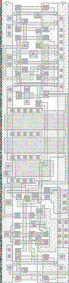
- Verified in silicon:
- using standard 0.18µm CMOS process
- low cell usage area of ~0.08mm² (31,000 transistors)
- low current consumption of 5µA at 1.0 V
- Hardware description language implementation allows design to be easily targeted to different technologies
- Design based on a highly flexible control-path / data-path architecture which makes it ideal for customization to a particular EPC Gen2 product
- Custom commands can be added and the memory organization modified with minimal design effort
- A high-level behavioral model and test vectors with 100% coverage are available to enable verification of the design and any customizations
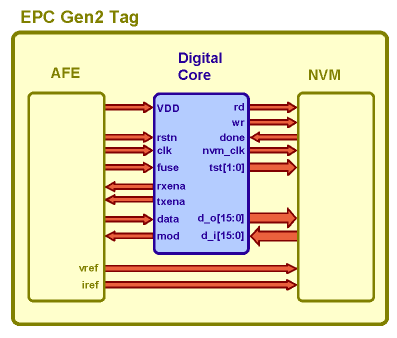
- Modular design can interface with general-purpose on-chip Analog Front-End (AFE) and Non-Volatile Memory (NVM) blocks
- RADLogic is able to aid in designing or sourcing suitable IP blocks depending on your needs
Core Functionality
Clock division
The digital core runs on a single master clock signal in the low megahertz range, provided by the AFE. It uses this to generate separate clocks for the comms block, control-path and data-path. The clock-divider is responsible for generating the sub-carrier signal for reply transmission, generating latch enable signals for the data-path and gating clocks off when a block is not in use to save power.
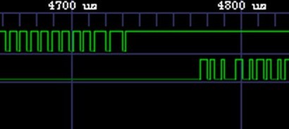
Communications
The digital core is capable of receiving Pulse-Interval Encoded (PIE) modulation at bit rates from 26.7 kbps up to 128 kbps. It is capable of sending FM0 coded replies at bit rates from 40 kbps to 640 kbps and Miller coded replies at bit rates from 5 kbps to 320 kbps. It transmits and receives frames Most-Significant-Bit (MSB) first and uses a Cycle-Redundancy-Check (CRC) for verifying the integrity of selected frames.
NVM Control
The digital core sequences 16-bit data reads from and writes to the NVM as required by incoming commands. It uses a hand-shaking mechanism so it can handle a wide variety of read and write access times.
AFE Control
The digital core gets its power, clock and reset signals from the AFE. In addition, the digital core receives demodulated command data from the AFE and replies with modulated sub-carrier data to be back-scattered. It also provides power management for the AFE by disabling the analog receiver and transmitter when they are not in use. Lastly, the core is provided with a fuse status input to allow proprietary test commands to be hard-disabled after wafer test.
State Control
The digital core features several state variables which persist between commands and short power breaks. The first is the Tag state which can be one of Ready, Arbitrate, Reply, Acknowledged, Open, Secured and Killed. This state variable allows the effect of a command to be dependent on the commands that have come before it. There are also the session flags S0, S1, S2 and S3 which record, for a particular session, whether the Tag has been inventoried. Finally there is the select flag SL which is used to filter Tags from the population based on memory contents. Since the standard requires that variables S1, S2, S3 and SL have persistence between power breaks, they must be custom-designed for a given technology.
Memory Organization
The EPC protocol specifies that the memory be organized into 4 separate memory banks, namely Reserved, EPC, TID, and User. The digital core performs the address processing required to map these banks to the single linearly addressed NVM.
Command Decoding
The digital core supports the following commands:
| Command | Code | Type |
|---|---|---|
| QueryRep | 00 | Mandatory |
| ACK | 01 | Mandatory |
| Query | 1000 | Mandatory |
| QueryAdjust | 1001 | Mandatory |
| Select | 1010 | Mandatory |
| NAK | 11000000 | Mandatory |
| Req_RN | 11000001 | Mandatory |
| Read | 11000010 | Mandatory |
| Write | 11000011 | Mandatory |
| Kill | 11000100 | Mandatory |
| Lock | 11000101 | Mandatory |
| Access | 11000110 | Optional |
| Test_Req_RN | 11100001 11000001 | Proprietary (Fuse intact) |
| TestRead | 11100001 11000010 | Proprietary (Fuse intact) |
| TestWrite | 11100001 11000011 | Proprietary (Fuse intact) |
The digital block first validates the received command. This involves checking that the command is supported for the current Tag state and is the correct length. For Query, Select, Req_RN, Read, Write, Kill, Lock, Access, Test_Req_RN, TestRead and TestWrite commands it will verify the integrity of the frame by running a cyclic-redundancy check. It may then check individual parameters within the command frame to prevent an illegal operation being performed such as writing to a locked block.
Once the command has been validated, it is executed. This normally involves an NVM read or write operation, change to the Tag state or generation of a new 16-bit random number.
After a potential execution, the digital block decides whether or not to send a reply. This depends on the command and whether or not it is valid. If required, the reply frame is generated containing parameters relating to the command.
Further Information
For more information about RADLogic's digital IP core please contact info@radlogic.com.au.
For more information about the EPC Gen2 standard go to http://www.epcglobalinc.org.